")
")


PILLARS is a new specific module, for pillars executive drawing starting from the decks structure.
This new module allows for the complete drawing of the pillars, and, it also enforces the checks as by European law requirement NTC D.M. 14 January 2008, and local circular C.S.LL.PP. 2009 n. 617.
Bars minimum diameter, distance between bars, spins insertion and the calculation of the critical area are suggested by this module. Furthermore, if you activate the check, in real time, the current reinforcement fits itself to the minimum provided by law requirement (NTC).
The PILLARS module substantially maintains the same input philosophy, enriching it with the reinforcement of the junctions (beams with pillars). Moreover the bars fit themselves according to any change in the pillar size: for instance, as showed in the following picture, by moving upwards, when the pillar gets thinner, the bar automatically bends, as well, aligning with it.
The procedure follows these steps:
1. Select and filter pillars
Starting from the drawing of the decks structure (it is necessary only the pillars presence) the pillars are selected. The Software is able to recognize and filter the pillars by same floor, dimensions, rotation, and, as a consequence, it can automatically organize the insertion of the reinforcement.
2. Insert stirrups
Once chosen the elements to reinforce, the user is asked to define: the cover-bar, the hook type and dimension (with a curved bar of 90° or 135°). Then, he should define the number of stirrups arms: 2 or 4, and their direction: x or y. According to NTC law requirement, the three stirrups fields are calculated and suggested (critical and central areas) with related distance and stirrups.
3. Longitudinal bars and crops
The diameters of the longitudinal bars are positionned in the angles (you can insert one or more) and along the sides: following X and Y direction.
With a “check” you define which bars will continue until the upper floor and which ones will terminate inside the slab, placed above the pillar itself.
Later, the user is asked to "define" the geometry and lenght of that part of the bar, that exceeds the level of floor.
In case of need for further reinforcement of junctions, some additional parts of bar can be inserted.
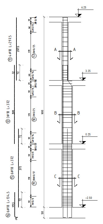
4. Bars for connection to foundation plate
Also these bars are proposed based on law requirement, NTC. You can insert the bars for connection to the foundation plate (position 16 in the picture).
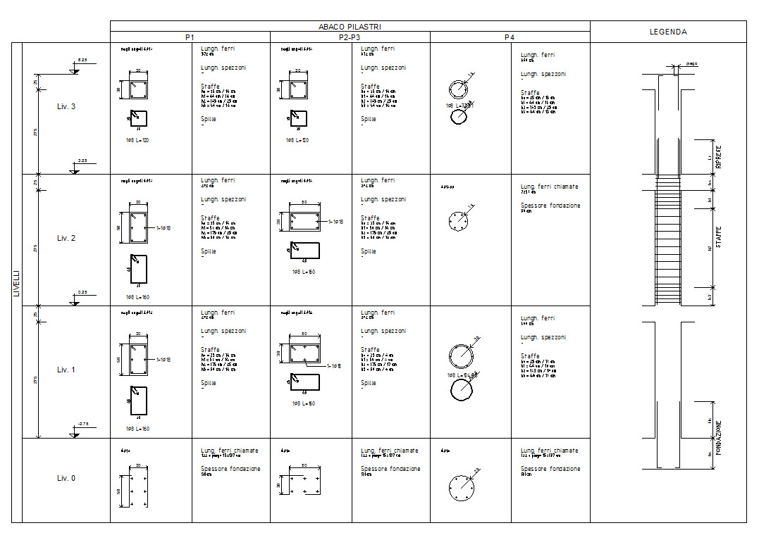
5. Summary Tables of pillars by decks
It is finally possible to obtain two different kinds of views, and consequently, of drawings of the pillars:
summary tables like that one below reported,
and, the front view of the pillar (with exploded view of each compounding elements).